 |
|||
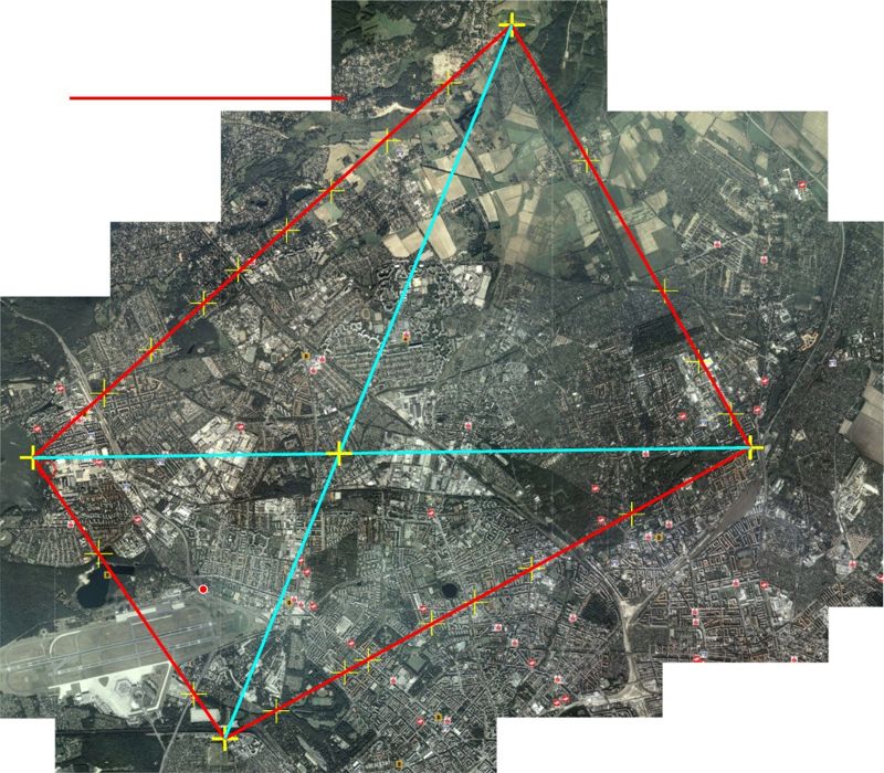
| The above image is a mosaic of aerial photos covering the area imaged in the strike photo. Landmarks along the edge of the strike photo were identified in the aerial photo and marked by a yellow fiducial mark (cross). Once enough landmarks were identified, red lines were drawn to indicate the border of the area imaged in the strike photo. Note that the area is not rectangular. This not only strengthens the claim that the aircraft was in a turn, but it was also nose down. Had the aircraft be in a turn, but level, the imaged area would have been trapezoidal in shape. This is demonstrated in Figures 3 through 5. | |||
 |
 |
||
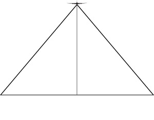
| Figure 3a | Figure 3b | ||
| In Figure 3a a B17 is flying straight and level. A camera in the aircraft is installed so that it looks at the nadir. The lens's angular field of view establishes
how much of the ground it can image. Figure 3b shows the situation from above. The green rectangle indicates the imaged scene in the ground plane. The corners of the imaged scene
all lie equidistant from the nadir putting them on the circumference of a circle. The circle has a diameter equal to the diagonal distance of the imaged scene. Consequently, if we
know the size of the negative, and the lens's focal length, then we know from the principal of right, congruent triangles, that the ratio of focal length (f) to the film diagonal
(d) is equal to the ratio of the aircraft's altitude (F), and the imaged scene diagonal (D). If we assume that lens focal length is 6.25", and the negative is 5" x 7", then d = 8.6".
For an aircraft flying at 26,000 feet, the imaged scene has a diagonal equal to (d/f)F, or (8.6/6.25)26,000 feet = 35,786 feet. Conversely, if we knew the imaged scene's diagonal
distance, we could then determine the aircraft's altitude, or more precisely, the distance from the principal point. What happens if the aircraft is not flying straight and level? Figures 4 show this situation |
|||
 |
 |
||
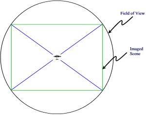
| Figure 4a | Figure 4b | ||
| If the aircraft has a bank angle of φ, the camera is no longer looking at the nadir. The imaged scene has a perspective that now sees a wider area farther from the aircraft, and less of the area nearer the aircraft. The imaged scene takes on the shape of a trapezoid, whose corners now lie on the perimeter of an ellipse. If the aircraft's nose is not level, this pushes one corner of the imaged scene even further away, and the opposite corner closer. This leads to the situation depicted in the mosaic above. | |||
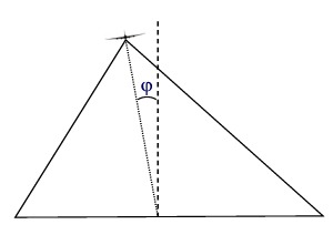
 Figure 5 |
|||
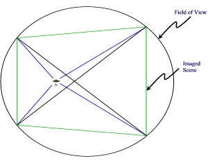
| In the above figure, a gray circle represents the field of view of an aircraft flying straight and level, with the rectangle (dashed lines) indicating the imaged
scene. If the aircraft rolls through an angle of φ the field of view is elongated into an ellipse. The imaged
scene takes on a trapezoidal shape. If the aircraft is not flying level, then the trapezoid is skewed. Is it possible, then, to determine the aircraft's attitude, altitude, and course just from the shape, and dimensions of the imaged scene, and the ellipse encircling it? The answer, is yes! Let us first look at the important elements of an ellipse. |
|||
 |
|||
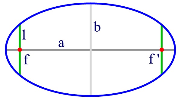
| An ellipse is a figure having two foci (red dots) labeled f and f' in the figure above. A line drawn from one focus to a point on the circumference, then to the
opposite focus is equal to twice the semi-major axis, labeled "a". The semi-major axis is the distance from the center of the ellipse to either of the farthest points
(called the apsides). The line labeled "b" is the semi-minor axis. A circle is a special ellipse where the foci are the same point. The distance from the center to the perimeter and back is then equal to the
diameter of the circle. The radius is 1/2 of the diameter. The green lines labeled "l" are the semi-latus recta, and are measured perpendicularly to the semi-major axis from the
focus to the perimeter of the ellipse. All three lines are related by a quantity called the eccentricity, "e". The eccentricity is the ratio of the distance from
the center to either focus and the semi-major axis. It an be shown then that b2 = a2(1 - e2) and l = b2/a. For a circle, the eccentricity
is zero. An important concept in our analysis is the relationship between an ellipse and a circle. If you draw a circle having a radius equal to the latus rectum of the ellipse, and if one focus of the ellipse is also the center of the circle (see Figure (5)), then the ellipse represents the circle tilted at an angle, φ. The eccentricity of the ellipse is then equal to the sine of the tilt angle: |
|||
|
e = sin(φ) |
|||
|
If we can determine what the eccentricity of an ellipse encompassing the imaged scene is, we are well on our way to discovering many things about the aircraft's location and orientation in space. That is the goal. |
|||